Mesh Customization
1. Define your mesh specification
After signing in, you will be directed to the Mesh Specification page. Click the “New” button ![]() to define a new mesh specification:
to define a new mesh specification:
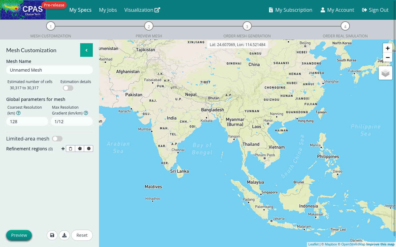
You will be guided step by step, to first (1) customize your mesh, and (2) preview it; then to (3) order a mesh generation. Finally you will (4) order a real simulation based on the generated mesh.

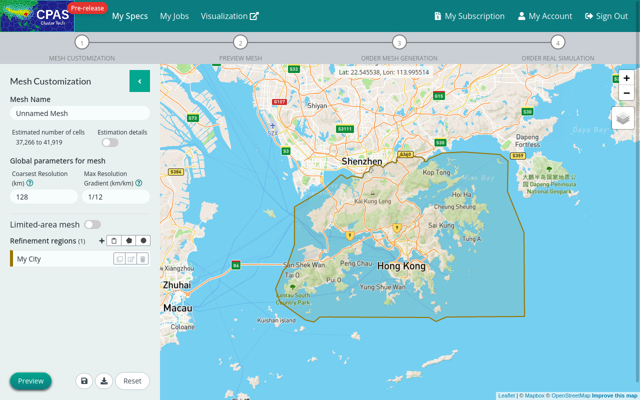
Firstly, you will enter the Mesh Customization page, providing an interactive map with a control panel on the left.
Our platform will help you to construct a suitable mesh composed of Voronoi cells of various sizes covering the globe or a limited area according to your specification. So before that, you need to specify refinement regions and define target resolution (i.e. cell size) of the mesh cells within each region you desire. Outside your refinement regions, sizes of mesh cells will be gradually relaxed to the specified coarsest resolution.
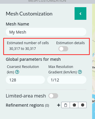
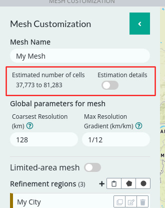
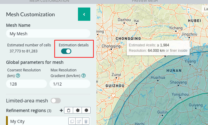
You will notice our preliminary estimated number of cells for the mesh which would change when you add refinement regions or change mesh resolutions.
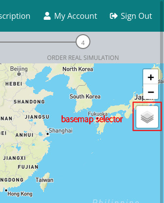
Before you start, you can change the basemap for a different style for the interactive map. Sometimes certain geographic information such as terrain, land use or administrative regions could assist you to define your desired mesh regions. Currently we provide 7 map styles.
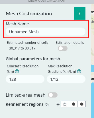
Step 1: Name your mesh
Step 2: Set global parameters for your mesh
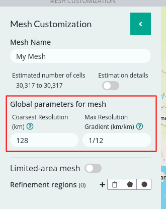 |
Coarsest Resolution (km) - The resolution you would like to set for the parts of the map outside of the to-be-defined refinement regions. For decent forecasts, a resolution of about 60 km is usually needed. The default 128 km resolution is a compromise for the Free Subscription level. (Default: 128 km. Maximum: 480 km) |
|
Max Resolution Gradient (km/km) - This is the largest rate of change in resolution with respect to distance. It acts as a limit for resolution transitions, ensuring that there are no abrupt changes of mesh spacing. The default value 0.0833 = 1/12 km/km means that a maximum 1 km-resolution change is allowed for every 12 km. |
Step 3: Add refinement regions
Your region of interest could be a single city, a county, a province, or areas of terrains; or you may have hierarchical regions of interest.
|
The default target resolution for a region (4 km) allows new users to observe how extreme resolution variations are handled by hierarchical time-stepping (HTS). Note that the resolution and area coverage of the region greatly affect the number of cells generated. If you have a low limit on the number of cells (e.g. 50,000 cells for Free Subscription), either draw a small region (city or metapolis scale) or change the target resolution to a larger value (e.g. 16 km for a province). |
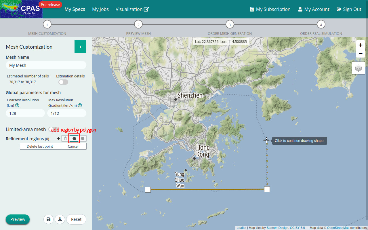
a) Add region by drawing polygon
Click the “Draw Polygon” button ![]() in the section of “Refinement regions” of the control panel. Then you can click the map to mark vertices of your polygonal region. Click the button “Delete last point” if you want to revert one step back. Click the first vertex to complete defining the region.
in the section of “Refinement regions” of the control panel. Then you can click the map to mark vertices of your polygonal region. Click the button “Delete last point” if you want to revert one step back. Click the first vertex to complete defining the region.
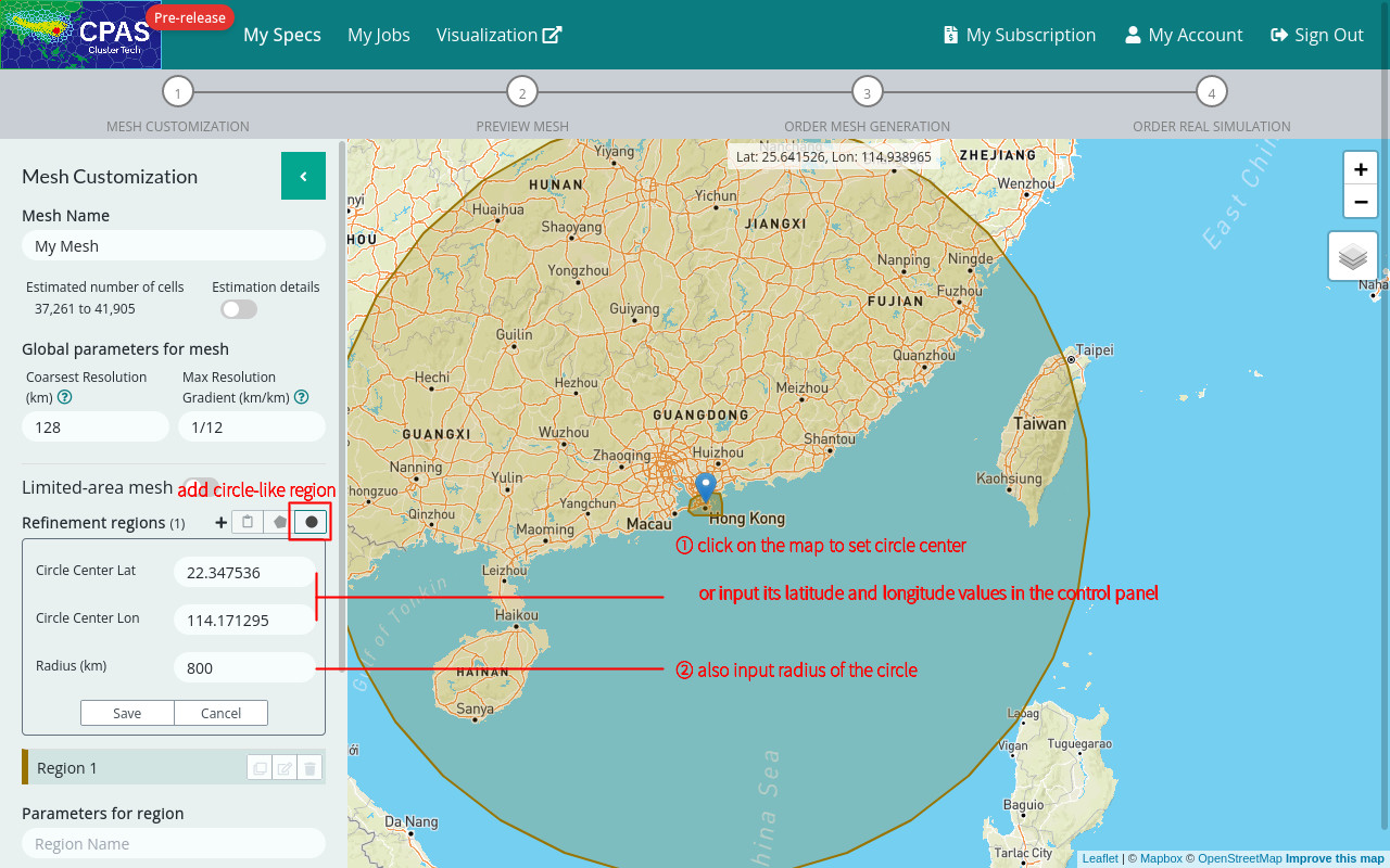
b) Add region by drawing circle
Click the “Draw Circle” button ![]() next to the “Draw Polygon” button. Set the circle center by clicking it on the map, or input its latitude and longitude values in the control panel. Also enter the circle radius. Once the setting is saved, the region would be circle-like, bounded by a good-enough fitting polygon indeed.
next to the “Draw Polygon” button. Set the circle center by clicking it on the map, or input its latitude and longitude values in the control panel. Also enter the circle radius. Once the setting is saved, the region would be circle-like, bounded by a good-enough fitting polygon indeed.
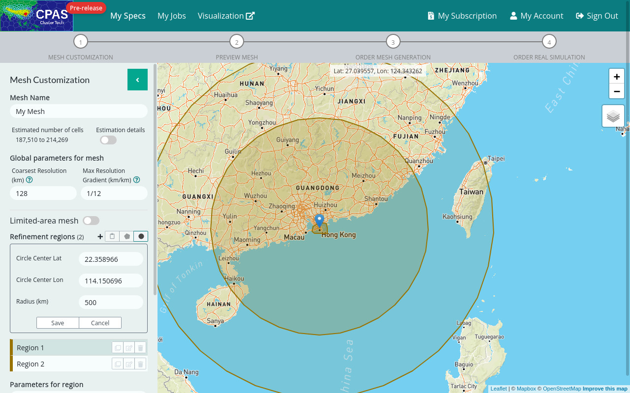
c) Add multiple regions
You can add multiple refinement regions. Regions can have areas overlapping other regions’ area, even inscribing them or being inscribed.
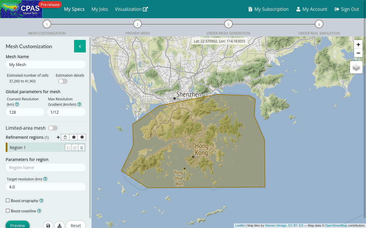
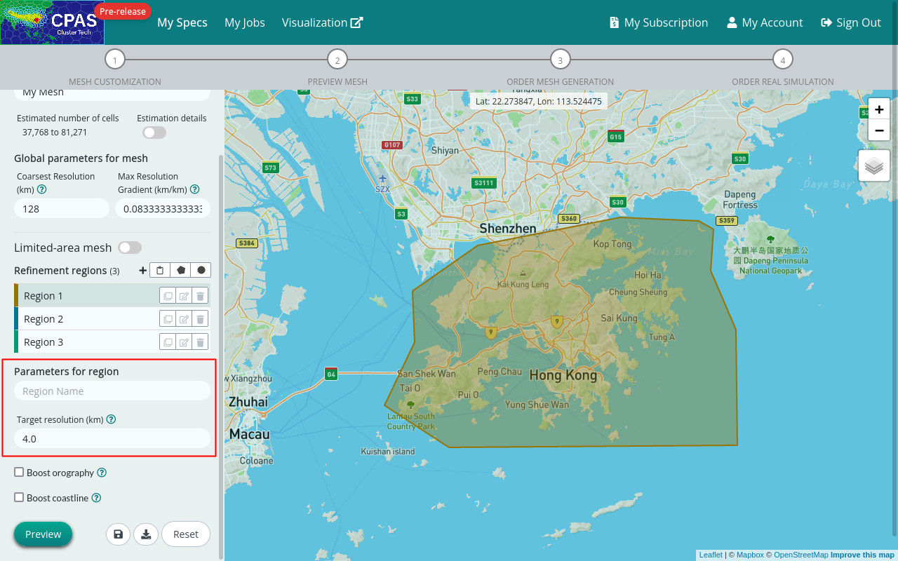
d) Specify parameters for regions
You can select each region in the region list and set region name and target resolution for it.
|
Target resolution (km) - The target distance between cell centers (variable dcEdge in MPAS-A) required within this region. (See MPAS-A user guide v7.0 - pp.65-66) |
When regions have overlapping areas, the intersection area would adopt the finest target resolution of the regions. A practical trick to “comment out” a refinement region, without deleting it, is to change the resolutions (including Ref. and Finest resolutions for orography and coastline below) to a larger number than its enclosing region, say, by typing a trailing zero to make the number 10 times larger.
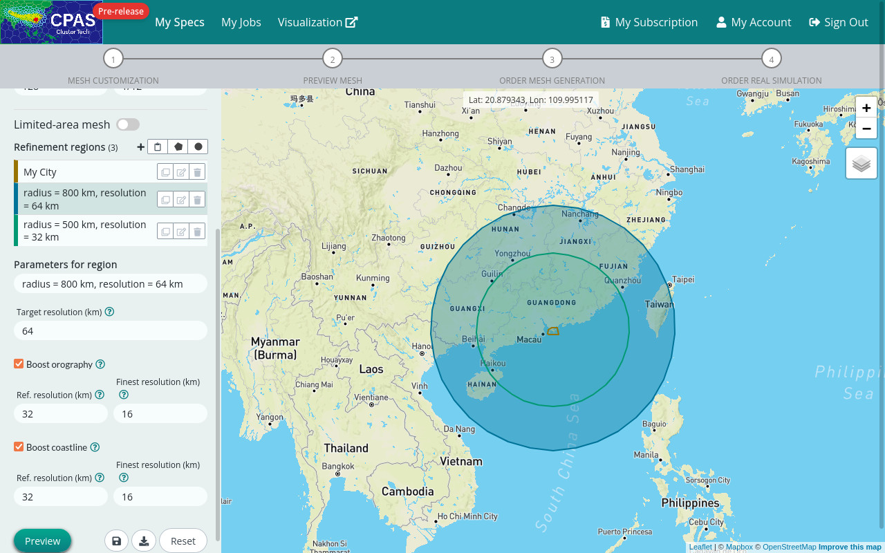
You can also select “boost orography”, which will boost resolution for areas with terrain height variation; and/or select “boost coastline”, which will boost resolution around land-water boundaries. For either selection, the resulting resolution will be at least as fine as the target resolution.
Boost orography
The MPAS-A/CPAS model averages out terrain height within a cell. So height variations of mountaintops and low lands will be smoothed out by each other in real simulation. Boosted resolutions for mountainous areas help to represent more terrain details, which might possibly provide more accurate prediction of wind speed in the lee sides of mountains.
|
Ref. resolution (km) - Reference resolution for regions with orography. This parameter is used by the algorithm for boosting resolution. Areas with mountain or hill use resolution around this reference resolution. The default value is 0.5 times target resolution. |
|
Finest resolution (km) - The finest allowable resolution for orography in the regions. The default value is 0.25 times target resolution. |
Boost coastline
Water has a strong effect on radiation and friction against air flow in contrast to land. Finer resolution around land-water boundaries (including sea, lake and rivers) in the model might help to resolve micro-weather details including land-sea breeze and lake breeze, etc.
|
Ref. resolution (km) - Reference resolution for regions with coastline. This parameter is used by the algorithm for boosting resolution. The default value is 0.5 times target resolution. |
|
Finest resolution (km) - The finest allowable resolution for coastline in the regions. The default value is 0.25 times target resolution. |
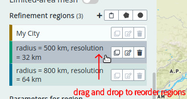
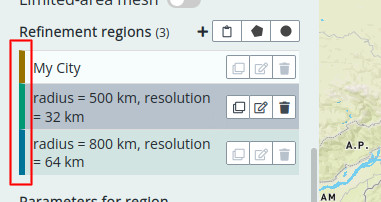
e) Reorder regions
You can reorder the regions in the list by dragging them.
|
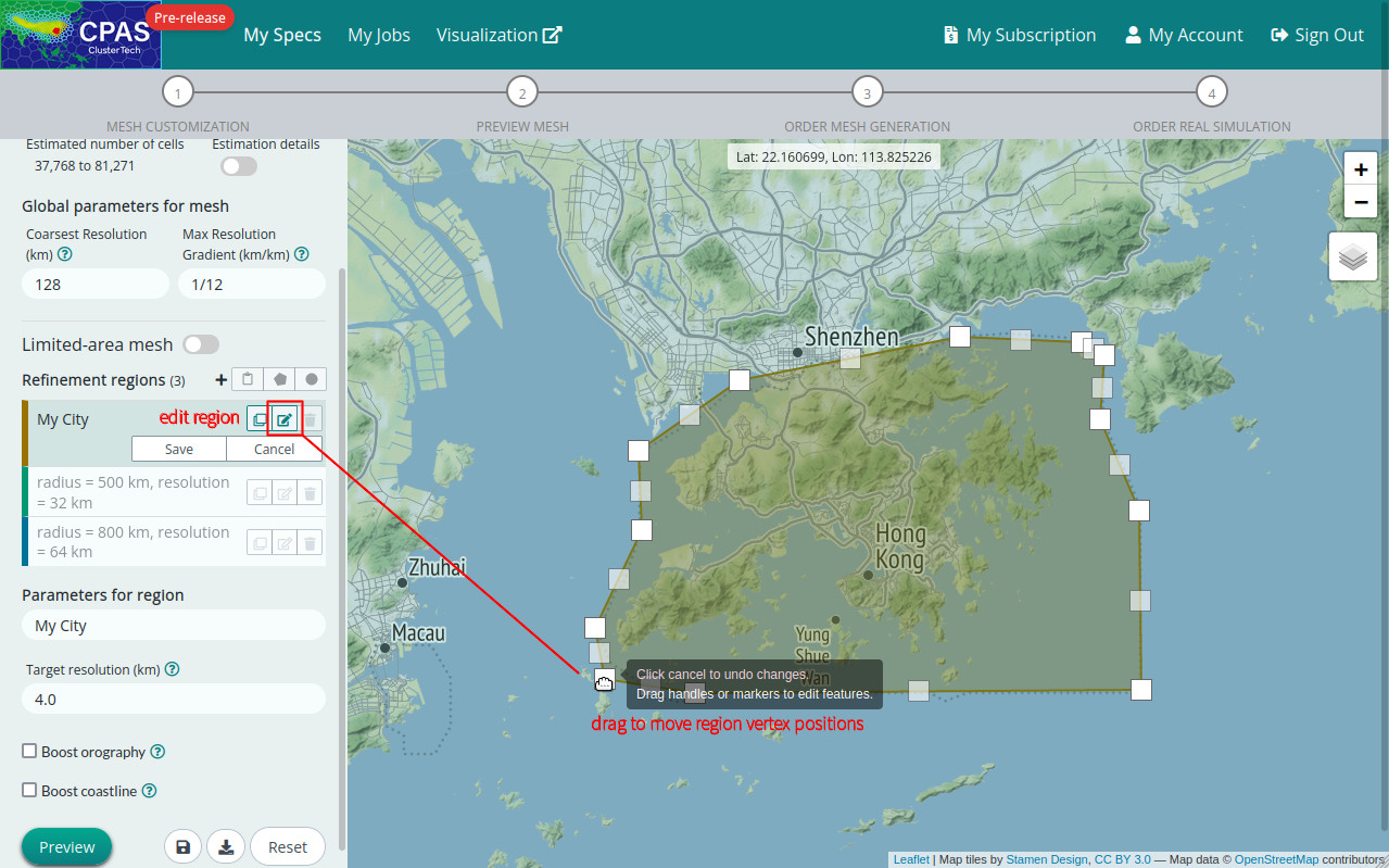
f) Edit the polygonal region
Clicking the “Edit” button ![]() , you can edit the polygonal region or circle-like region (which is a polygonal region indeed). You can drag the polygon’s vertices to adjust their positions. To add more vertices, drag the ghosty (translucent) squares at the polygon’s edges to fit your need. To delete an unwanted vertex, simply click it. Lastly, click the “Save” button to adopt your change, or click the “Cancel” button to withdraw it.
, you can edit the polygonal region or circle-like region (which is a polygonal region indeed). You can drag the polygon’s vertices to adjust their positions. To add more vertices, drag the ghosty (translucent) squares at the polygon’s edges to fit your need. To delete an unwanted vertex, simply click it. Lastly, click the “Save” button to adopt your change, or click the “Cancel” button to withdraw it.
g) Delete a region:
Click the “delete” button ![]() of a listed region you do not want, and a dialog box will pop up asking for your final confirmation. Click the red “Delete” button for no-return deletion; or “Cancel” button to think twice.
of a listed region you do not want, and a dialog box will pop up asking for your final confirmation. Click the red “Delete” button for no-return deletion; or “Cancel” button to think twice.
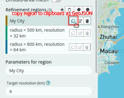
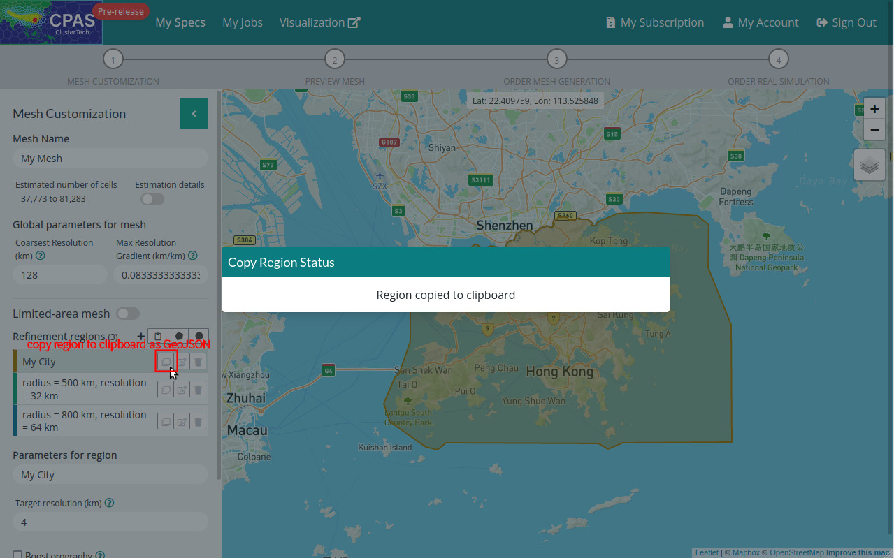
h) Backup a region, and reuse it in another mesh:
Your work of region specification can be backed up and replicated in another mesh specification. First, copy a configuration GeoJSON of a listed region to your OS clipboard as text by clicking its “copy” button ![]() . Then, you can paste and save the configuration text somewhere for future reuse.
. Then, you can paste and save the configuration text somewhere for future reuse.
 |
 |
Finally, to reuse the configuration of the region in another mesh specification, go to that mesh customization page. Click the “paste” button ![]() at the “Refinement regions” section to reveal a text box. Paste the configuration text on it, then click the “Import” button to confirm.
at the “Refinement regions” section to reveal a text box. Paste the configuration text on it, then click the “Import” button to confirm.
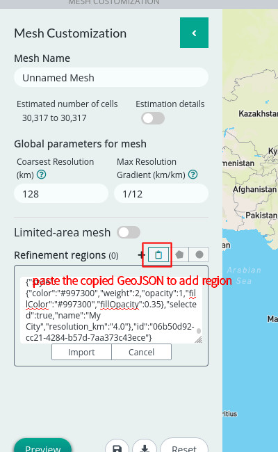
The region will then be imported finely.
Step 4 (Optional): Set limited-area mesh
Instead of using a mesh covering the whole globe in real simulation, CPAS supports you to run real regional simulation for a limited-area mesh. You can switch on the limited-area mesh trigger, and specify a limited-area domain you want by adding a polygonal region or circle-like region.
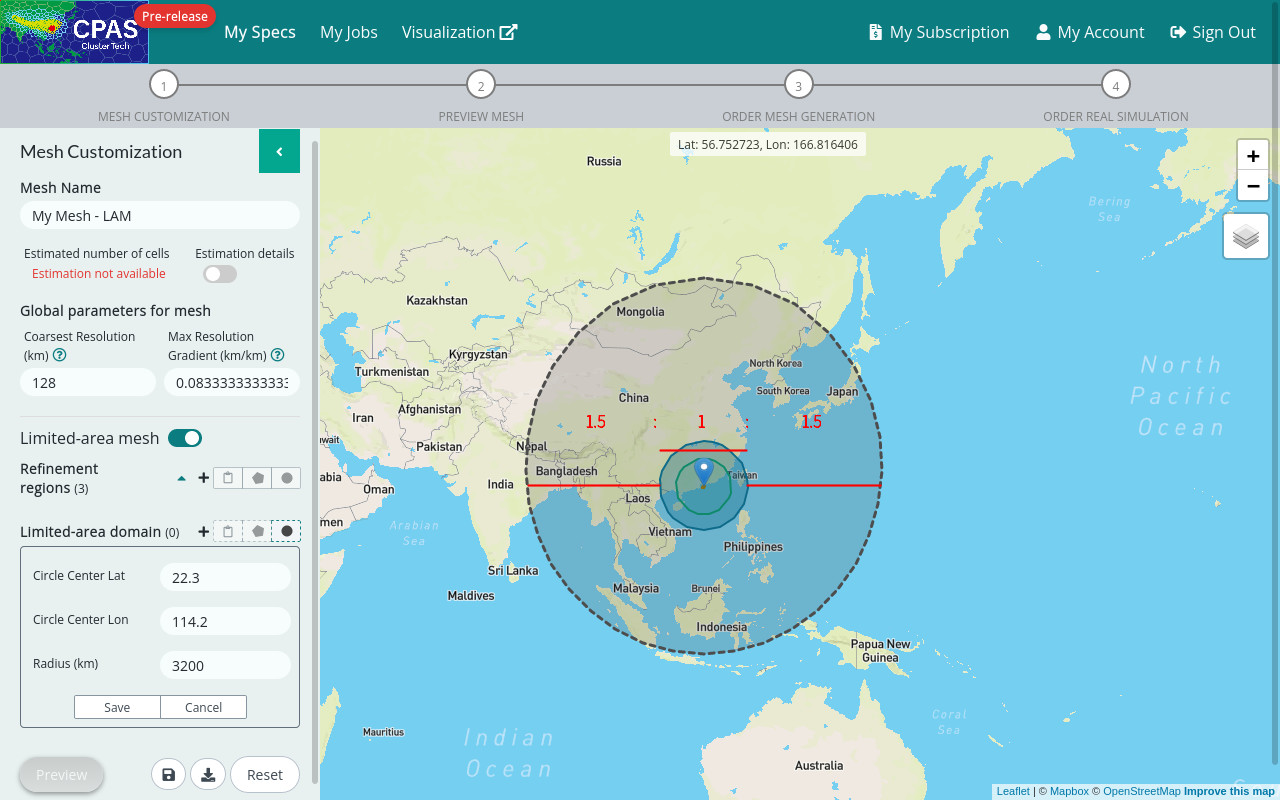
The mesh will be generated within the limited-area domain, plus the relaxation and specified zones extended right outside the specified domain (See: MPAS tutorial practice guide - Regional MPAS: overview). Beyond the refinement regions, mesh resolution will be dilated to the specified coarsest resolution. When CPAS runs real simulation for the mesh, an external weather data source will be needed to supply the lateral boundary conditions. A general advice is to specify the limited-area domain boundary from your interested region some distance of roughly 1.5 times the region size or more away, so as to let the interested region stay away from adverse boundary effects.
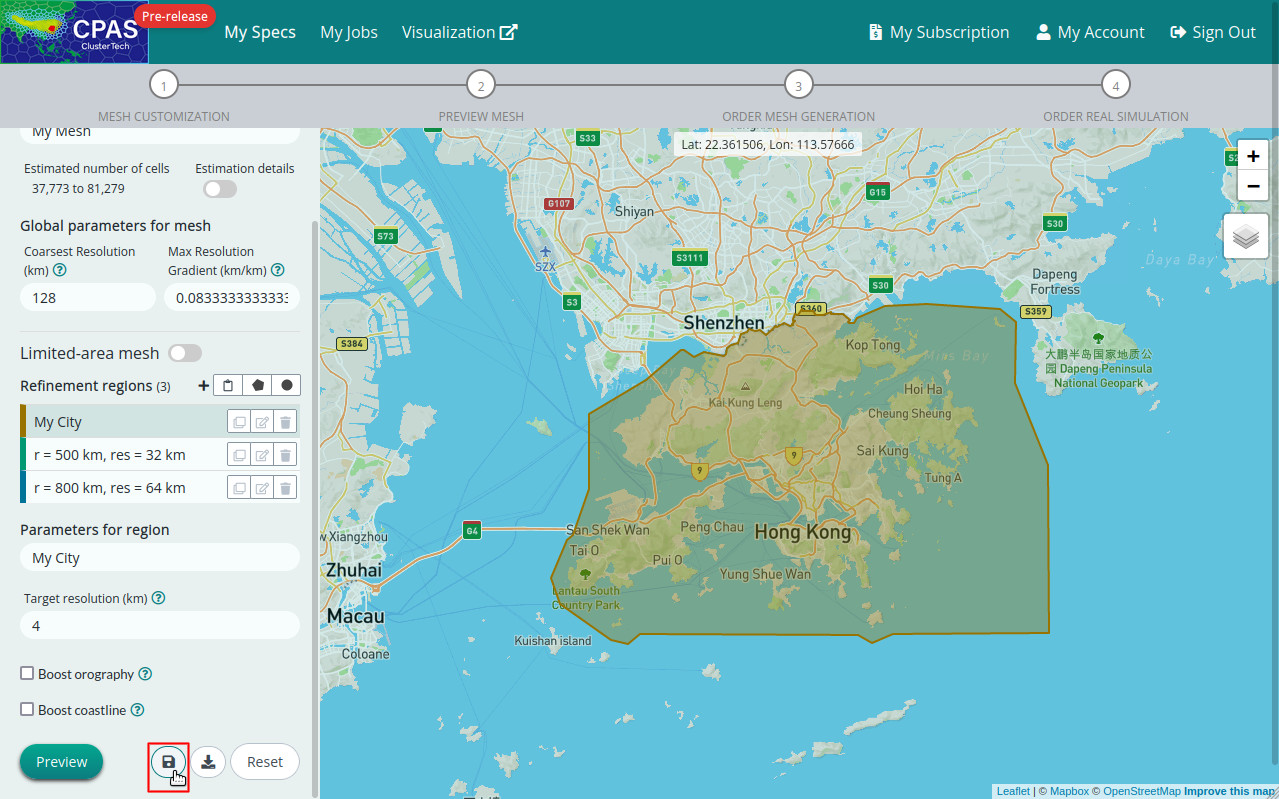
Step 5: Save you mesh specification
The set of regions and parameters specified for a mesh is called a Mesh Specification, or a Spec for short. Save you mesh specification by clicking the “Save” button ![]() in the bottom of the left panel.
in the bottom of the left panel.
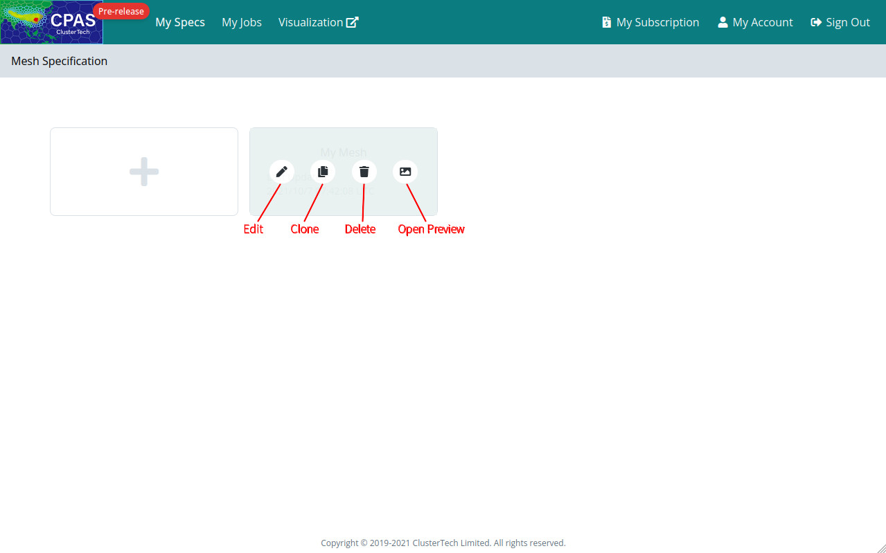
The saved specifications can be found in the “Mesh Specification” page by clicking “My Specs” in the top menu.
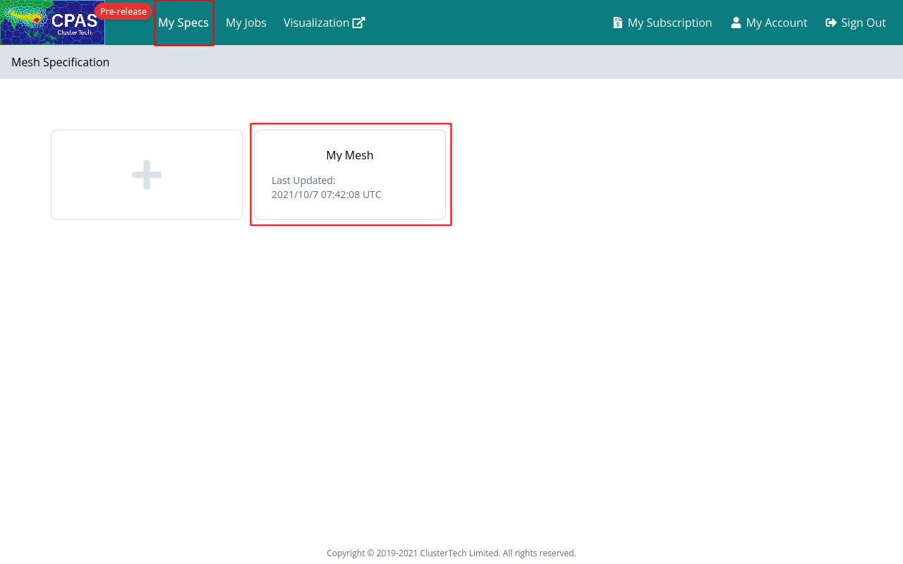
You can “Edit”, “Clone”, “Delete” and “Open Preview” for a saved specification.
| Back to Mesh Customization | Next |